Komplexe Einrichtung am Beispiel "
Hauptplatine"
Wird überarbeit!
Vereinfachte Prinzipdarstellung eines Compuersystems:
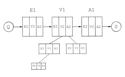
E1 = z.B. Tastatur
V1 = .......Rechner
A1 = z.B. Monitor
E2(E1) = Benutzer-Schnittstelle (Tastschalter)
V2(E1) = Prozessorplatine
A2(E1) = USB-Schnittstelle
E2(V1) = USB-Schnittstelle
V2(V1) = Hauptplatine
A2(V1) = Schnittstelle (Grafikkarte)
E2(A1) = VGA-Schnittstelle
V2(A1) = Prozessorplatine
A2(A1) = Benutzer-Schnittstelle (Bildschirm)
E3(V2) = BUS-Schnittstelle
V3(V2) = Central Prozessor Unit (CPU)
A3(V2) = BUS-Schnittstelle
E3(A2) = BUS-Schnittstelle
V3(A2) = Prozessoreinheit
A3(A2) = z.B. VGA-Schnittstelle
E4(V3) = Befehlsregister
V4(V3) = ALU (Arithmetik Logik Unit) der CPU
A4(V3) = Programmierbare PORTS